
| benf.org : other : speccy usb keyboard |
About every year or so, I get a sudden urge to do some undergrad hardware....
Fortunately, LanceR is actually pretty good at the hardware side (heck, he got me to solder in a straight line - that's nigh on a miracle), so we occasionally end up hatching some hard/soft hybrid plan, which is great, and goes nowhere, because we're both extremely important and busy people. (And handsome. Don't forget the handsome.)
However, this has been on my todo list for about 2 years now, and since I noticed something similar on hackaday, I thought I'd better get it finished before someone else does!
Consider the humble ZX Spectrum....
You can pick these up on ebay for about a tenner (15 quid if you're unlucky). They're full of nostalgia, and make me quite weak at the knees.
I got one of said devices on ebay (on a whim) about 2 years back, and it's been sitting gathering dust... as soon as I pulled it apart, it became obvious that the keyboard membrane was a wreck (25 year old Polyethylene seems to dessicate badly) - simply pulling out of the connectors caused it to fall apart. Fortunately there's a brilliantly retro guy selling new replacement membranes, so another (well deserved) Ł15, and we're back in business.
You might have seen the excellent "Entire PC Speccy" - here, this chap used bits from a modern USB keyboard, and (since he had the entire PC in the case) remapped the keyboard. Since we're after a proper USB keyboard, remapping on the host seems really lazy (I can't exactly remap random colleagues' keyboards in work), so we decided to do it ... properly.
The speccy membrane from RWAP, scanned in (click for big)
... (the colouring was actually done in about 5 minutes using paint shop pro - the wand tool really is good!)... while there's tonnes of docs on this stuff, it's pretty obvious what's going on here. Alternate a high/high impedance low signal across the 0-4 'pins' on the left, and read the resultant signal level on the right (pulling low to drain it.) - i.e. if pink (2) is powered, and I read yellow (3) as high, then '8' is pressed.
So now it's a matter of hacking together a really dirty prototype using an 18f4550 board LanceR built ages ago, and slightly modifying the MicroChip USB HID sample (I'm driving the 5 pins with portA, and using portD pulled with 10k for the return signals)
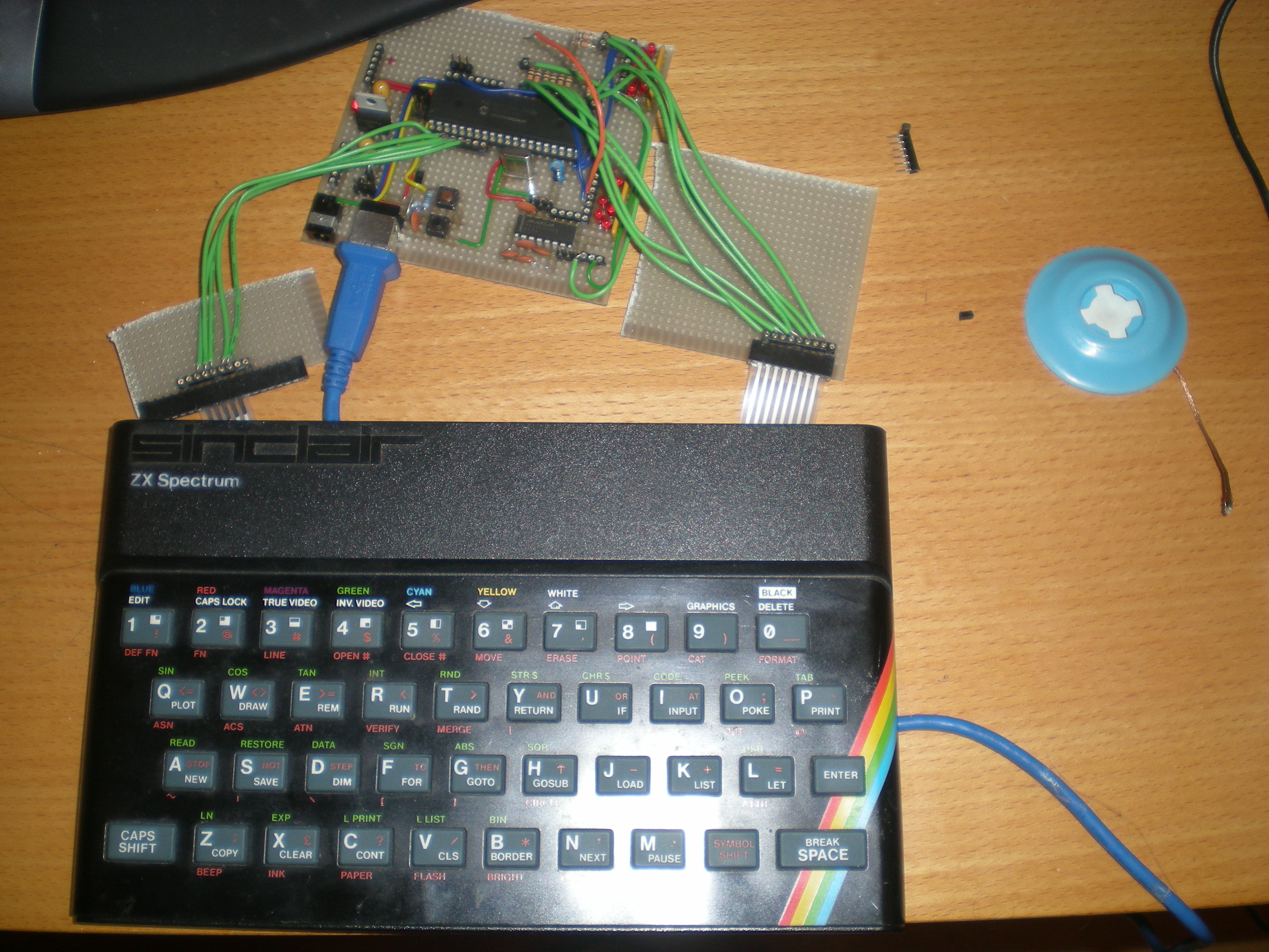
And here it is in action! (xvid codec req'd)
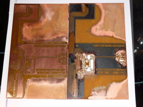
Lance has been working his magic, and etched up something which looks much less hacky!
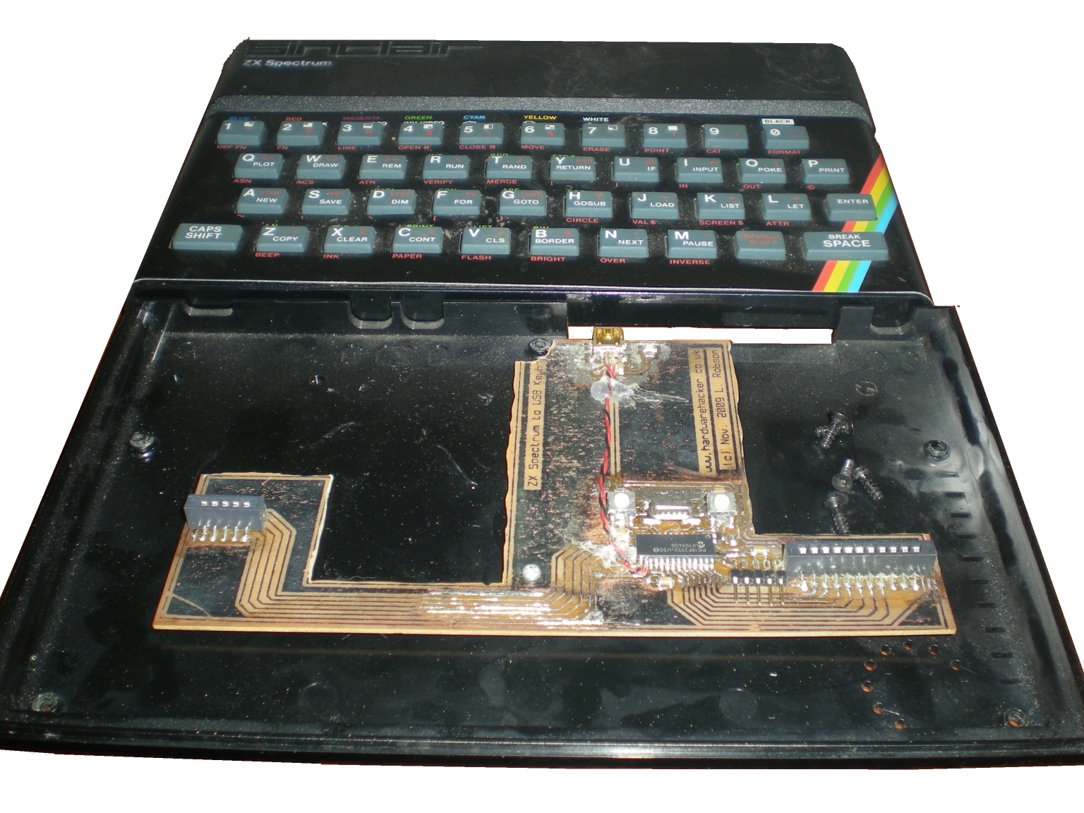
The final board once fitted
.... more doccing, and the software to come .... and now we've gotten this far, we might even finish it!
| Last updated 11/2009 |